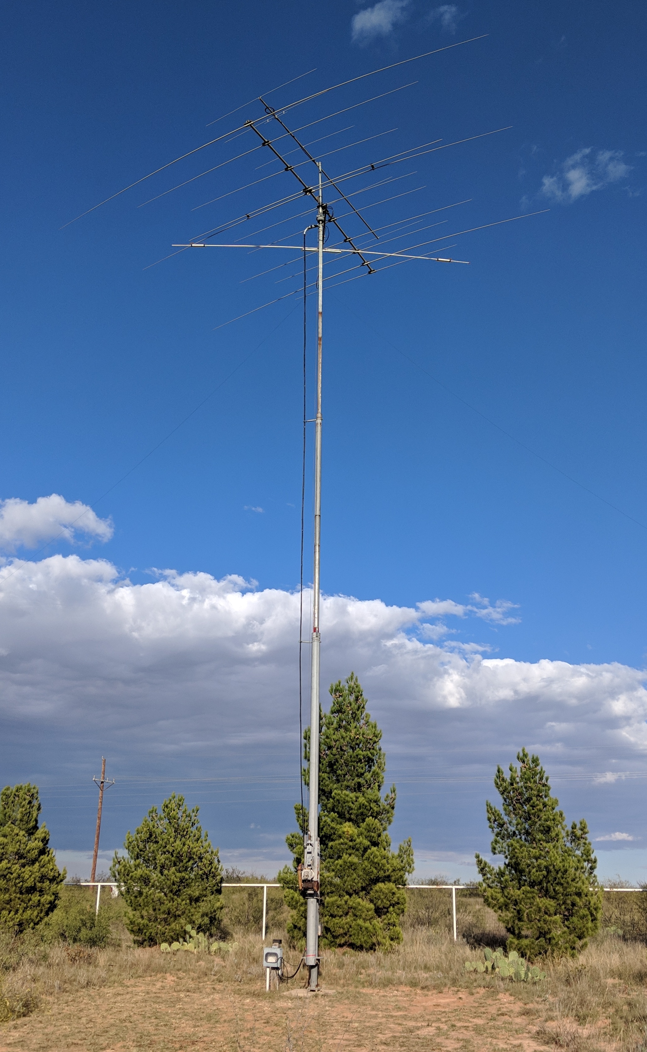
I’ve owned a US Tower MAB-550MDP crank-up tower since about 1990. This is a 55′ tubular crank-up with motorized winch and positive pull down. My current QTH is the fourth location I’ve installed this tower. It’s been up at this location since 2002.
A couple of months ago I decided it was about time to replace the coax on the tower. I have three runs of coax going to a Force 12 C19XR yagi, a 5 element 6m yagi, and a 12/17m driven element from a Mosley TA-33M-WARC. Two of the runs of coax were Davis RF “Bury-Flex” and the other, which was to the 6m antenna, was unknown.
There are three coax standoffs that I bought with the tower, Since I first installed the tower I’ve always attached the coax to each standoff with the standoffs offset from the one above so the coax would form a loop as the tower is lowered. Seemed like a good idea so the top standoff wouldn’t have to support the weight of all of the coax plus the rotor cable.
I normally keep the tower cranked down to about 40′. The problem with that system is when the tower isn’t up the wind would blow the loops around the standoff below it. I’d then have to get a pole and try to get the loops clear to be able to crank up the tower. Because of that I didn’t crank the tower up very often.
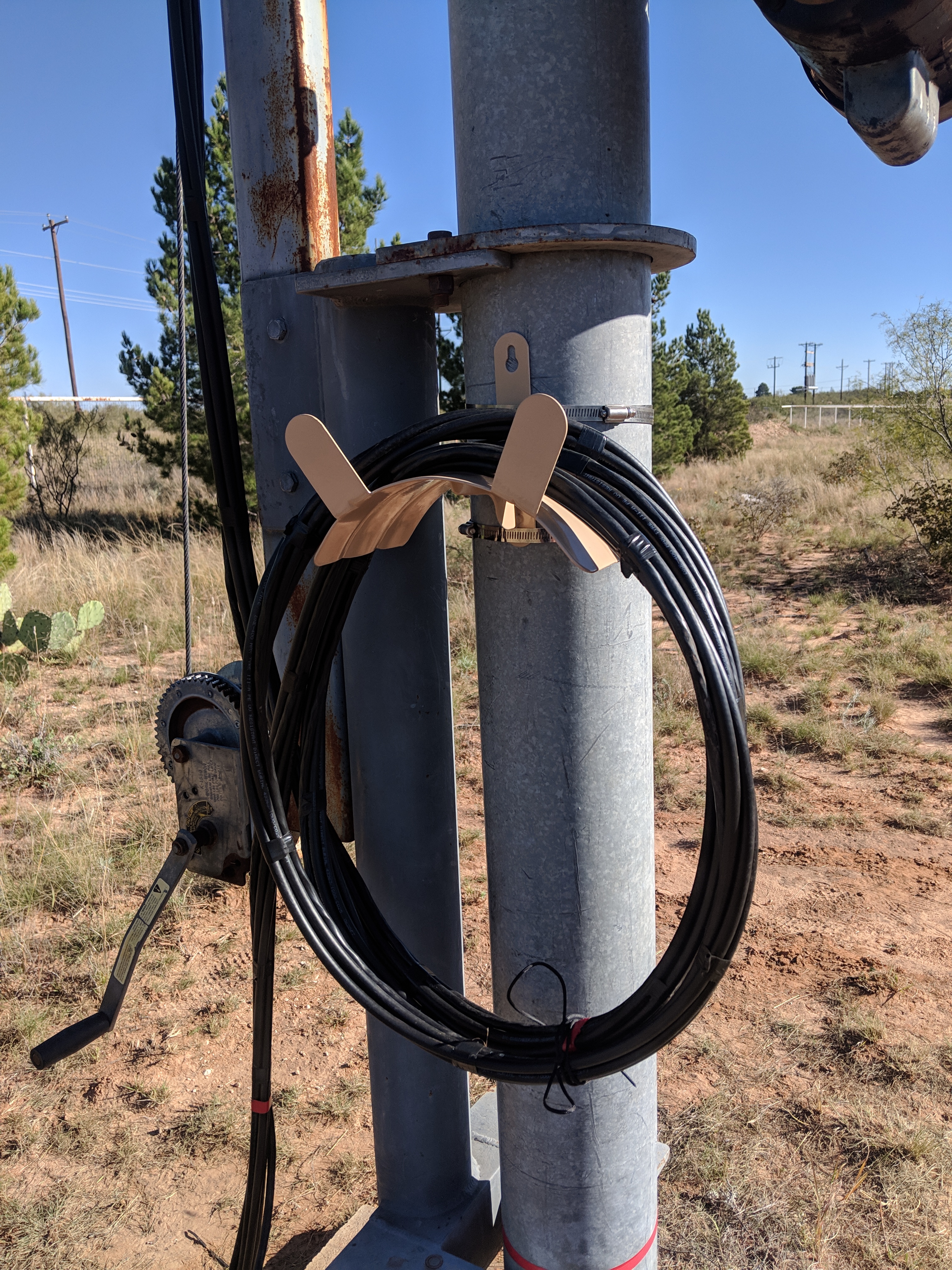
Since I was replacing the coax I decided to route it differently and hang the coax from the top standoff and drop the cable down through the other two standoffs. Not wanting to have a sharp angle where the coax was attached to the top stand off I bought a piece of 90 deg PVC conduit. I split the top off with a band saw. I attached the 90 to the top standoff and laid the cables in it. That worked well.
I should have done this years ago! Makes for a much neater installation and easier cranking up and down of the tower. I installed a garden hose hanger to hold the cable when the tower isn’t raised completely.